Aesthetic Myoelectric Prosthetic
AMP is a hand prosthetic that uses myoelectrography (EMG) to create an interactive display for tour groups in the Weldon school of Biomedical Engineering at Purdue.
Team
- Alyssa Wan (Project Manager)
- Tim Ausec (Design Lead)
- Helen Fivecoate (Firmware Lead)
- Neha Karthik (Member)
- Asem Aboelzahab (Advisor)
1. Description
The purpose of AMP is to provide prospective biomedical engineering students with an inspiring impression of the output of biomeidcal engineering students at Purdue.
I took part in this project as part of the Purdue EPICS program under the guidance of Asem Aboelzahab and in collaboration with my teammates listed above. The major aim of our team was to create a prototype that could move each of the five fingers independently.
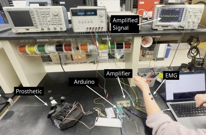
The system is quickly summarized into its key components as below:
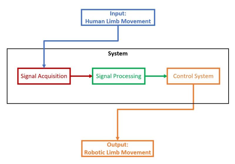
The key idea is that EMG signals are read off of the user’s arm and fed into a microcontroller that controls the movement of the prosthetic.
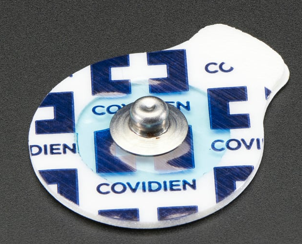
1.1 Signal Acquisition
EMG signals are acquired with gel electrodes that can be stuck onto and taken off of the body repeatedly, such as the one shown below:
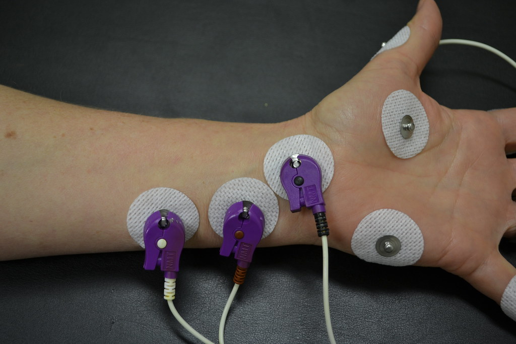
The signal for each finger is referenced to a “ground electrode,” with one electrode in different locations of the arm for each finger. Thus, the system had 6 total inputs. The below image is a good representation of the setup for a user:
The signals received directly off of the electrodes are measured to be in the single milli-volts range. Additionally, the wires (up to 50cm long) leading off of the electrodes can easily couple to the surrounding environment, introducing EMI. Thus, a filtering and amplification circuit is used to create a usable signal for the microcontroller.
1.2 Signal Processing
A differential analog multiplexer designed for low-noise, high-speed applications is used to select the desired finger signal (e.g. pinky). This differential signal is sent to a differential amplifier whose output is rectified, filtered, and amplified and sent to the micrcocontroller.
The circuit was simulated with LTSpice to obtain the desired results (e.g. 0 input -> 0 output, full input -> 5V output).
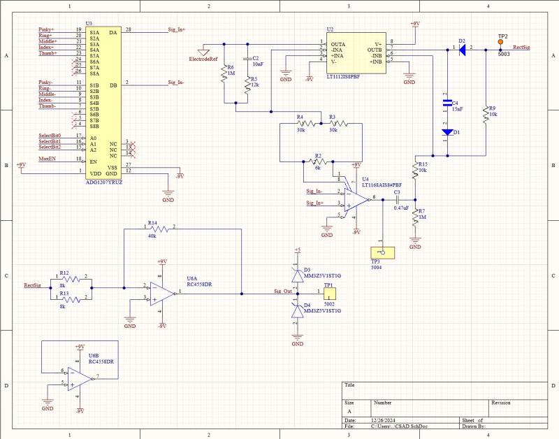
It should be noted that zener diodes are used to clamp the output between 0 and 5V. The op-amps provide the necessary current to bias the zeners into the full reverse breakdown region.
1.2.1 Power
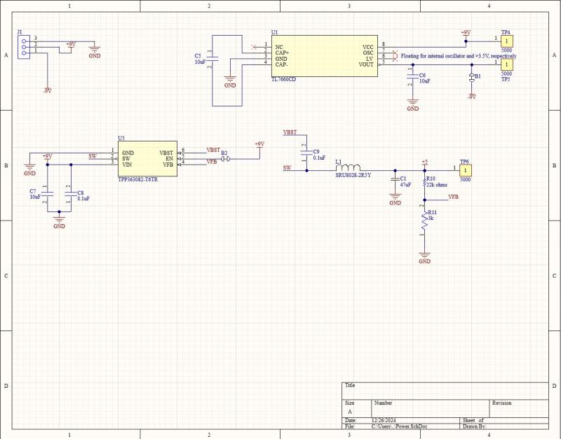
The team desired a compact and simple power solution for the system. We devised the use of an off-the-shelf power converter in order to make the system safe for future teams to work on, as designing for and working with mains voltage is no task for beginners. This 9V converter supplies power to the whole system, including the signal processing system, the microcontroller, and the prosthetic’s motors.
A switching buck converter is used to supply 5V to the motors and microcontroller. On further reflection, it would have been prudent to separate the microcontroller line from the motor line, as the inductive motor load introduces transients on the 5V line that either interfere with microcontroller operation, or which need to be overcompensated in comparison to a solution where the motor supply line is allowed to fluctuate while the microcontroller acts as a small capacitive load on its own rail.
A charge pump is used to provide a -9V rail for the op-amps present in the circuit, since they take low current (max 100mA range).
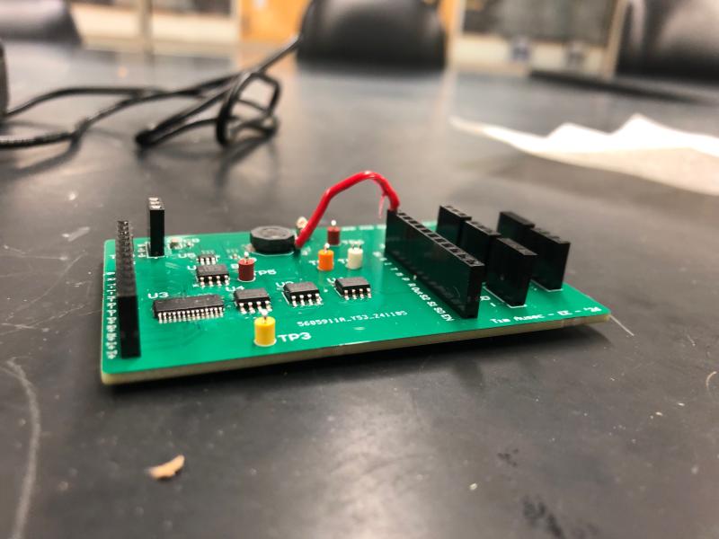
The below picture shows the fully assembled PCB designed in Altium Designer.
1.3 Control System
Since the main aim of this team was to create a prototype to demonstrate independent finger movement, an Arduino Uno was used as the microcontroller for its ease of use and availability.
The Uno takes in the amplified signal and runs it through an averaging filter to reduce the bandwidth of the system. The philosophy here is that the response time of the digital loop is easier to control than the analog filtering circuit, so the user experience can be enhanced quickly through tweaking parameters in a program instead of components on a PCB.
This signal is then mapped to what amounts to be a coarser quantization for the position of the finger motors. In this iteration, the motors are (PWM) servo motors, so the position is directly applicable to the motor drive.
2. Results
Huge strides were made towards individual finger movement, including a reliable hardware platform and adjustable code. For the first time, the team was able to complete the signal chain from EMG to servo in a smooth way. Additionally, clear documentation was generated that laid out the design philosophy and next steps for next semester’s team.
However, we were not able to properly distinguish each finger from each other finger with the algorithms that we tried to employ on the data with our dinky little Uno. Additionally, manufacturing delays introduced a time crunch for proper hardware integration, leaving a messier-than-desired product in our wake.
3. Challenges
The major challenge faced was determining which finger to move based on the inputs.
In order to quantify the problem and start making headway with it, I first generated CSVs of the data by recording the voltage output of the amplifying circuit with an oscilloscope. I put the electrodes in the “target” position on my arm and recorded the output of a flex with each finger with the electrode in that position. Thus, for each target finger, I generated 5 CSVs. I did this for all 5 fingers, generating 25 CSVs.
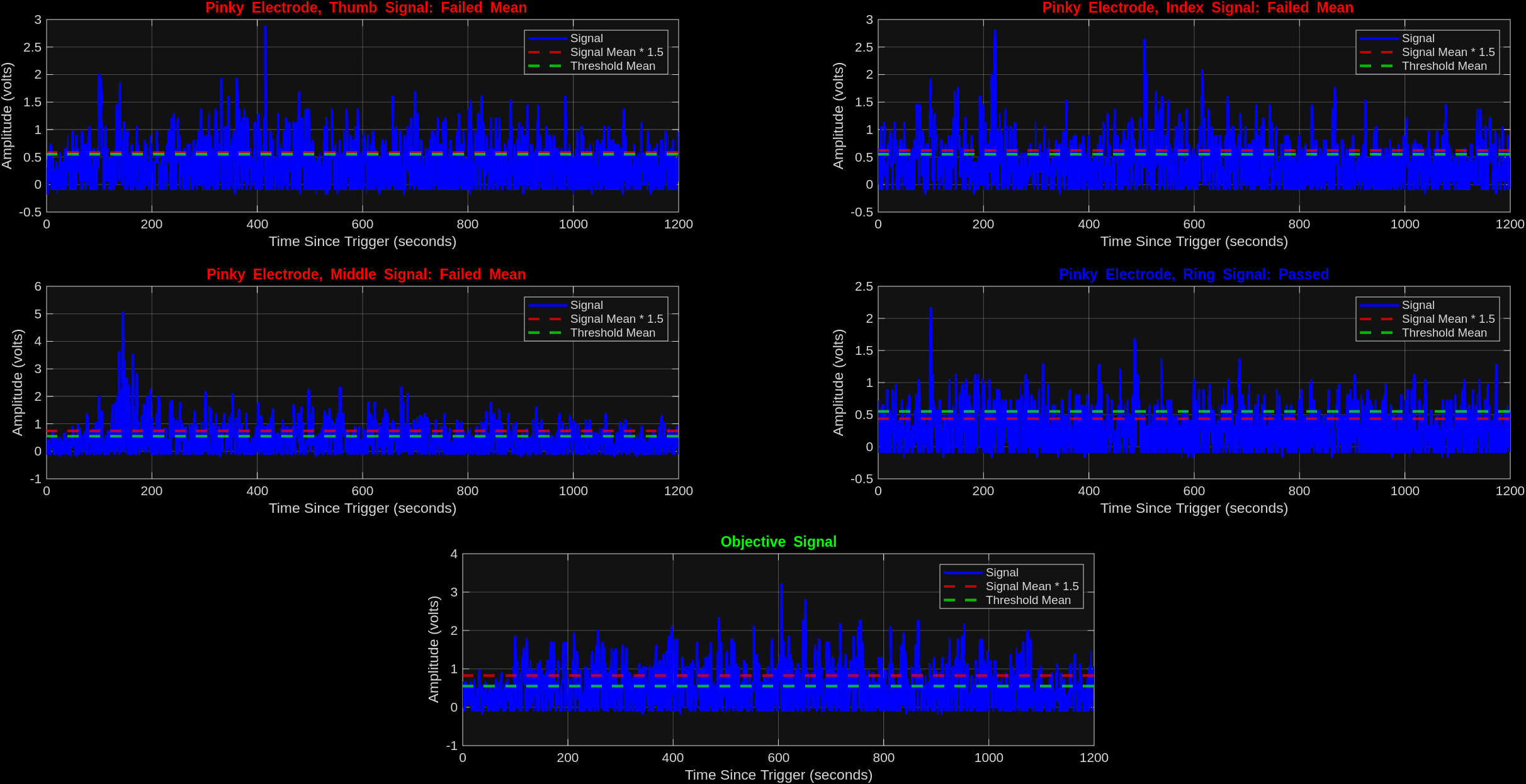
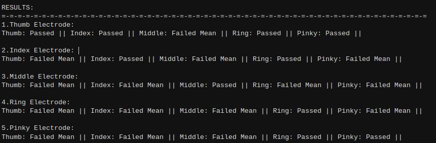
I then fed this data into a MATALB script. This script determined whether or not the mean of the off-target signals were a certain threshold multiplier above the mean of the on-target signals. This helped determine if a naive Darwinian (“pick the strongest signal”) approach was appropriate and to quantify the level of crosstalk present between fingers. It turns out that this approach is incredibly innapropriate.
Thumb as target (best):
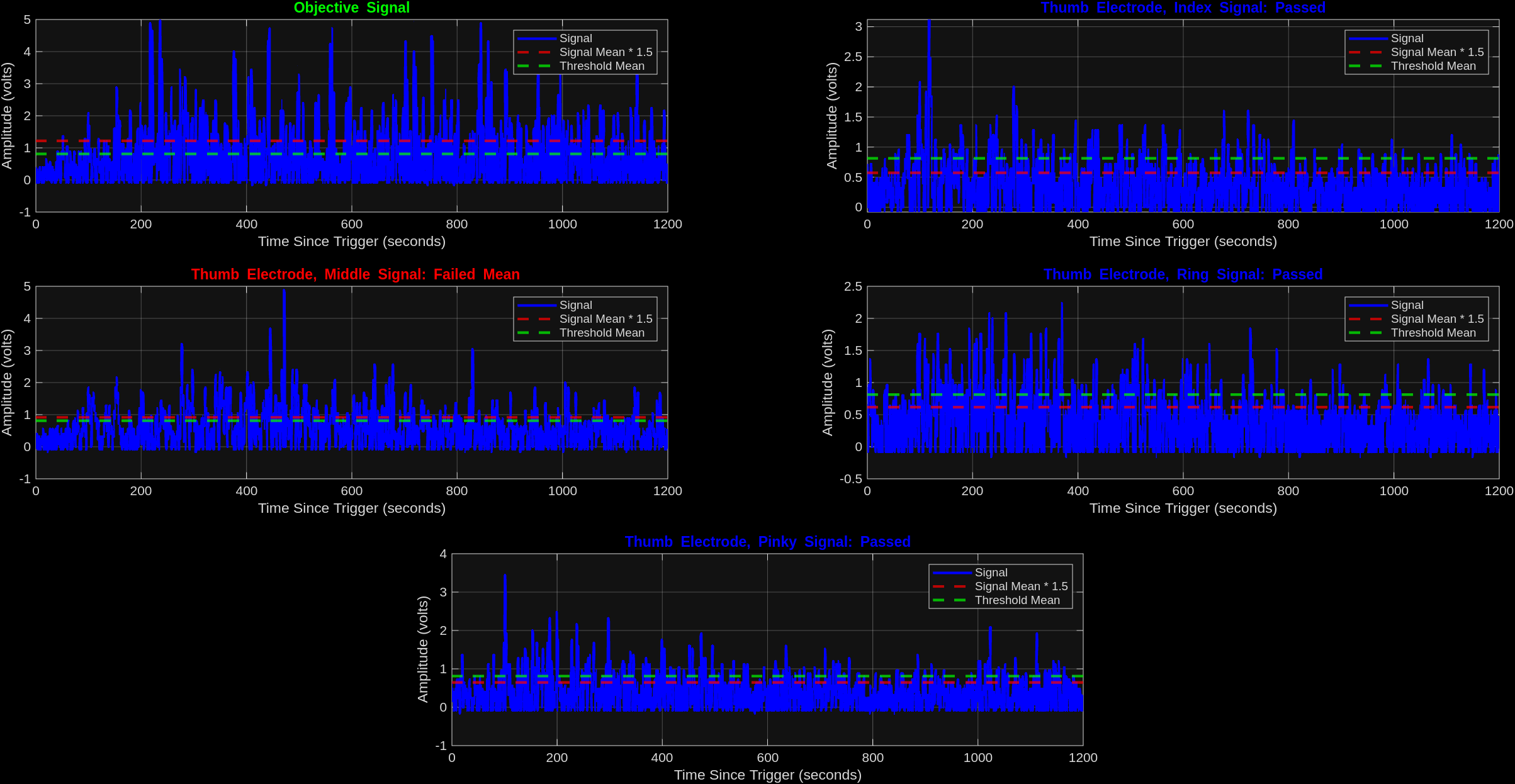
At this point in the project, we had run out of time to understand how to tackle this problem. In hindsight, the exploration of any data science model (not even necessarily machine learning!) would probably have bore fruit.
If I were working on this problem now, I would have generated many samples from the above data generation process from many different people and found the model that minimzed the error on the dataset available. This likely still could have been done on a dinky Uno, but it could be easily swapped for a more powerful micro if needed.