DC Discharge Gridded Ion Thruster
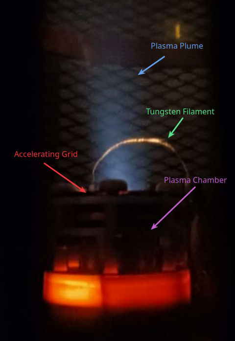
The Rose-Hulman Electric Propulsion Group (RHEPG) Direct Current Discharge DC Discharge Gridded Ion Thruster (DC GIT) is an undergradute-built-and-tested ion thruster.
See our peer-reviewed publication here.
Contributors
Authors:
- Ishaan Mishra (Team Lead)
- Tim Ausec (Electrical Lead)
- Hakkı Onur Dördüncü (Mechanical Design)
- Adam Jirovec (Mechanical Design)
- Justin Lin (Experimental Design)
- Miguel Vasquez Lopez (Experimental Design)
Team:
- Rebecca Testa (Electrical Design)
- Cesar Osornio (Experimental Design)
- Philip Pounds (Mechanical Design)
- William Geoghegan (Mechanical Design)
Technicians:
- Brian Fair (MiNDS Lab Technician)
- Jack Shrader (Electrical Engineering Technician)
- Roger Sladek (Physics and Optical Engineering Department machinist)
Advisors:
- Dr. Ben Mertz (Main Advisor)
- Dr. Dan M. Goebel (Design Reviewer, Secondary Advisor)
1. Description
Ion thrusters are a form of electric propulsion that accelerate ions to generate thrust. The simplest and most common application is active attitude control for satellites. The main advantages of an ion thruster to a classic combustion engine are low vibration and high fuel efficiency, measured as specific impulse. Ion thrusters can achieve a specific impulse 25x-35x more than that of classic combustion engines, which also means they generate much lower thrust, on the order of mN.
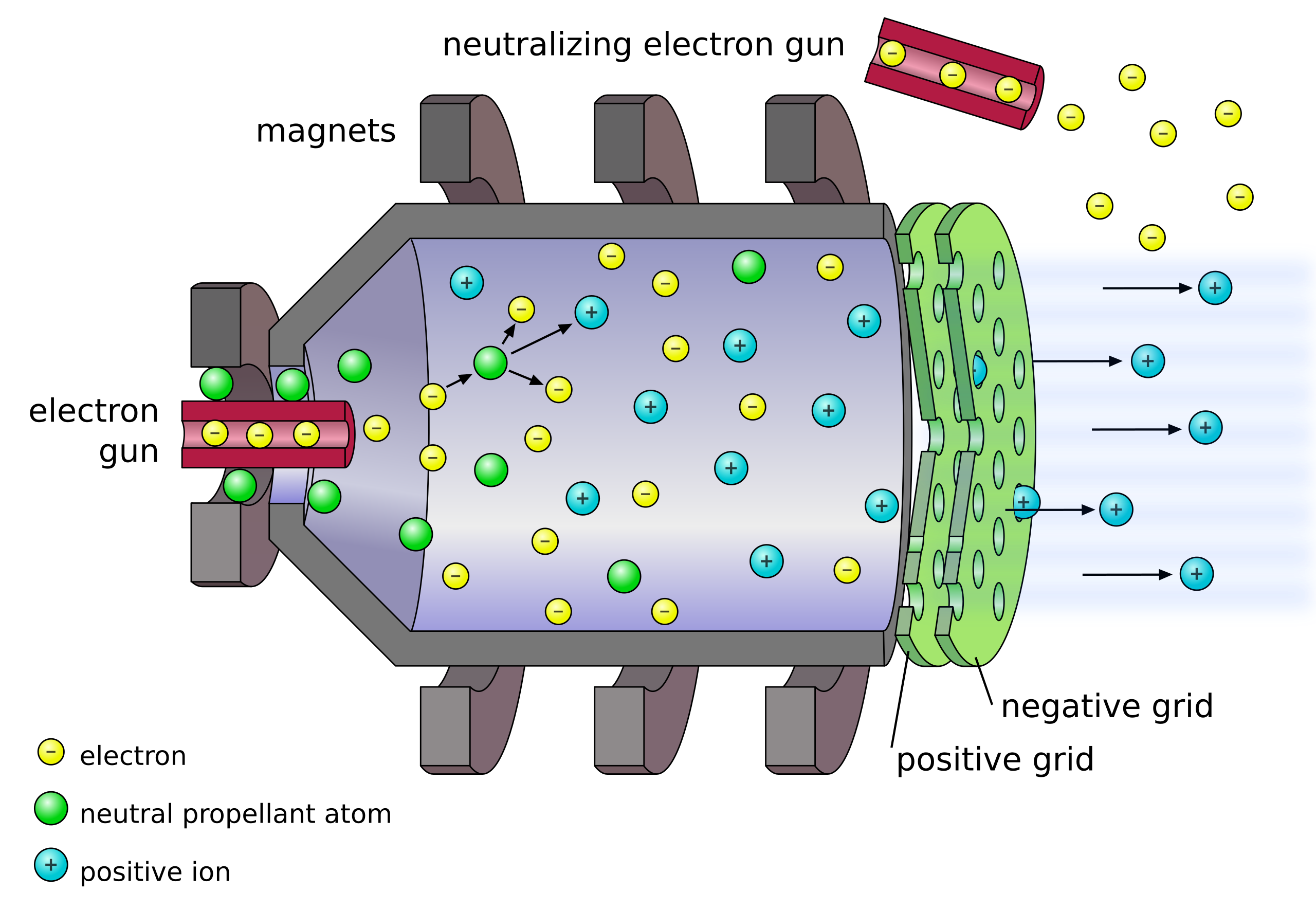
A gridded ion thruster (GIT) uses an electrostatically biased grid to accelerate ions which produce thrust. A DC GIT uses a cathode (or “electron gun”) to induce ionization in a gas (usually a noble gas, like Argon) and accelerates the resulting ions with the grid.
At the time, the study of electric propulsion had high barriers to entry at the undergraduate level, including expertise and funding. The goal of the RHEPG DC GIT was to document and share the process by which a fully-undergraduate group could develop and test a DC GIT system to lower these barriers for future groups.
In practice, this project was an exercise in translating academic works into engineering solutions.
A major source used was Fundamentals of Electric Propulsion: Ion and Hall Thrusters by Dr. Dan Goebel and Dr. Ira Katz.
1.1 Theory
A quick tromp through some basic theory is useful for understanding system performance and the importance of key decisions. Specific impulse $I_{sp}$ is the ratio of thrust to massflow. Therefore, high $I_{sp}$ means high fuel efficiency. This leads to the equation
$$I_{sp}=\frac{\dot{m_i}v_i}{\dot{m_p}g}=\frac{v_i}{g}\eta_m$$Where:
- $\dot{m_i}$ is the massflow of ions exiting the thruster.
- $\dot{m_p}$ is the massflow of propellant entering the thruster.
- $v_i$ is the exit velocity of the ions from the thruster.
- $g$ is the acceleration due to Earth’s gravity.
- $\eta_m=\frac{\dot{m_i}}{\dot{m_p}}$ is the propellant utilization efficiency
Therefore, two options exist for controlling the specific impulse of an ion thruster:
- Ion velocity $v_i$
- Propellant utilization efficiency $\eta_m$
$\eta_m$ is affected by the efficacy of the propellant delivery system and propellant choice. In an ideal world, where propellant choice is the only factor at play:
$$\eta_m=\frac{\dot{m_i}}{\dot{m_p}}=\frac{\frac{I_b}{e}M}{\dot{m_p}}$$Where:
- $I_b$ is the current through the grids.
- $e$ is the charge of a proton.
- $M$ is the ion mass.
$v_i$ is affected both by propellant choice and the electromagnetic environment in the chamber.
In a simple world where only the basic electrical design of the thruster contributes to the electrodynamics of the system, conservation of energy can be applied:
$$-\Delta U = \Delta KE$$$$eV_b = \frac{1}{2}Mv_i^2$$
$$v_i = \sqrt{\frac{2eV_b}{M}}$$
Where:
- $V_b$ is the voltage between the grids.
Notice that combining these equations yields:
$$I_{sp}=\frac{I_b}{g}\sqrt{\frac{2MV_b}{e}}$$Meaning that maximizing $I_b$, $M$, and $V_b$ maximizes $I_{sp}$. Since higher $V_b$ increases $I_b$, it is crucial that a high $V_b$ is maintained when considering propellant efficiency. This is why modern thrusters have $V_b$ in the kV (or, equivalentlly, power in the kW).
1.2 System Overview
The RHEPG DC GIT “straightforwardly” implements the conceptual design as above. The major system-level design considerations are as follows:
1.2.1 Propellant
Noble gasses are used as propellants in ion thrusters due to their low reactivity, reducing corrosion and increasing reliability. The most common propellant in this field is xenon due to (1) high density (high $M$) and (2) low first ionization energy (decreases input power). However, xenon is quite expensive due to its rarity. Other propellants used include iodine, argon and krypton.
Argon is chosen for its low cost relative to all of these options. SpaceX does the same thing :).
1.2.2 Magnetic Confinement
The purpose of the magnetic confinement system is to keep ions and electrons from being absorbed by the chamber walls. This is desirable because (1) ion-wall collisions corrode the chamber, and (2) the longer an electron stays in the chamber, the more ions it can generate, increasing electrical power efficiency and propellant utilization.
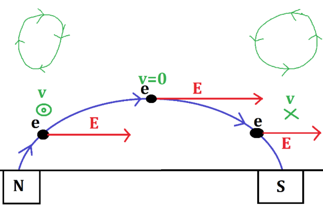
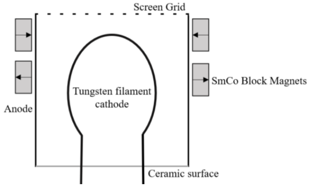
Magnetic fields confine charged particles with the same principle used in cyclotrons. The Lorentz force law shows us that charged particles in a constant magnetic field causes those charges to spin. The design of the magnetic confinement system should ensure that this spinning is on the same axis as the rest of the chamber. See the below diagram for more information.
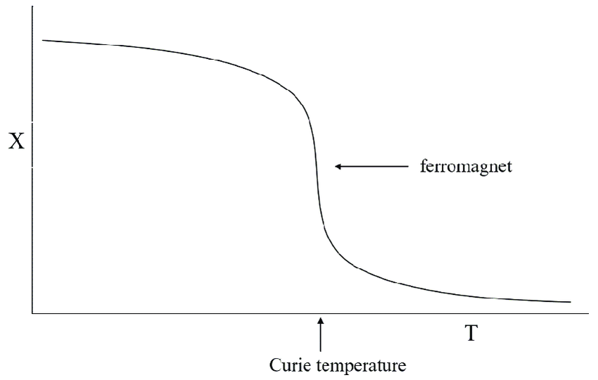
Permanent magnets are used to generate magnetic fields to reduce cost and complexity. A major consideration for this system is the Curie temperature. The below figure shows how magnets can lost their magnetism at the Curie temperature. This effect is permanent in many materials. The environment in the chamber is incredibly hot. Plasma-wall collisions typically bring the wall temperature up to around 200C to 300C. As such, care must be taken to pick resilient magnets that have a Curie temperature much higher than the wall temperature AND operate well in the expected temperature range.
For this purpose, samarium-cobalt magnets are used as the permanent magnets. We found this to be the best choice to balance temperature performance with cost and other material properties.
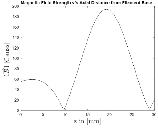
The below figures show the general setup within the chamber of the magnets, as well as the magnetic field strength as a function of position within the chamber.
1.2.3 Cathodes
Two cathodes are utilized in the DC GIT: the discharge cathode and the neutralizing cathode. Both cathodes utilize thermionic emission to generate free electrons.
When a material becomes extremely hot, and especially when the material is subject to an electric field, the electrons in that material can jump off of the surface.
These free electrons have two purposes in the DC GIT. (1) To ionize the propellant (discharge cathode), and (2) to neutralize the outgoing plasma plume (neutralizing cathode). The outgoing plasma plume must be neutralized, or it will be attracted to the body of the thruster, damaging the body and decreasing thrust through electrostatic forces.
The relevant equation is the modified Richardson’s law:
$$J(E,T,W)=A_GT^2exp\{-\frac{W-\Delta W}{kT}\}$$With:
- $W$ is the work function of the material
- $\Delta W=\sqrt{\frac{q_e^3E}{4\pi\epsilon_0}}$ is a correction factor on the work function for the presence of an electric field
- $T$ is the temperature of the material
- $A_G$ is a parameter that depends on the material
- $k$ is the boltzmann constant
To determine the expected temperature of the filament in operating conditions, the Stefan-Boltzmann law is used:
$$P=A\epsilon \sigma T^4$$In the below figure, the curve shows the emitted current versus temperature of the filament for a tungsten filament under an electric field.
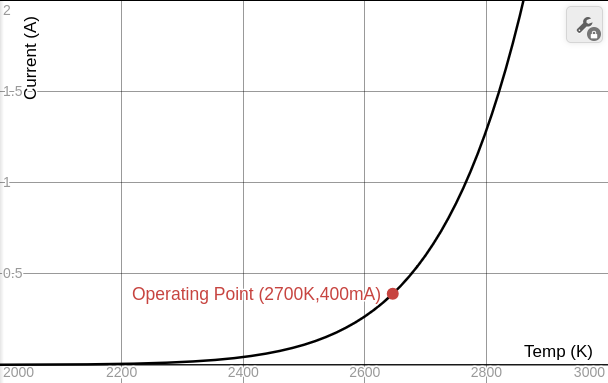
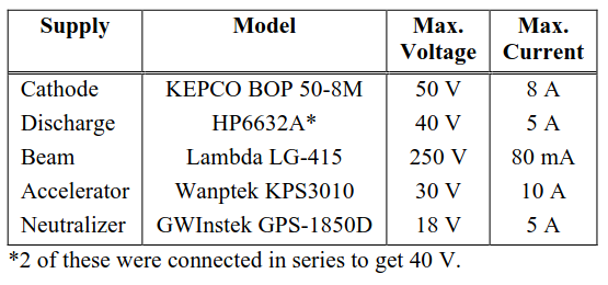
In our thruster, the electrical supply operating point for the discharge cathode was 40V @ ~600mA, whereas the neutralizing cathode operated at 7.6V @ 4.5A.
1.2.4 Potential Distribution
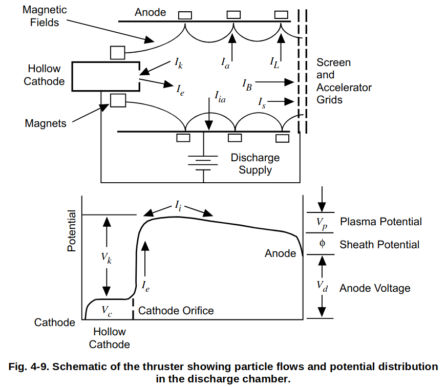
The above figure demonstrates the desired potential distribution across the length of the thruster. The main considerations are:
- There must be a large potential difference between the discharge cathode and the anode wall to maximize ionization efficiency.
- There must be a large potential difference between the screen and accelerator grids to maximize specific impulse.
- The anode wall must have a higher potential than the plasma so that ions exit the chamber instead of colliding with the anode wall.
1.3 Subsystems
The team was split into 3 subteams: electrical, mechanical, and experimental.
1.3.1 Electrical Design
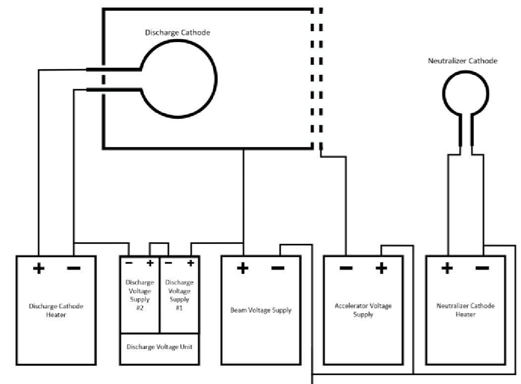
The purpose of the power processing unit (PPU) is to provide an electrostatic environment that efficiently generates and accelerates ions. In short, the PPU:
- Supplies current to the discharge and neutralizer cathodes.
- Generates a voltage gradient that (a) accelerates electrons emitted from the discharge cathode into the chamber walls, and (b) accelerates ions out of the thruster.
The below two figures show the PPU schematic and specifications for each power supply. The electrical equipment was provided by the RHIT EE shop. Special thanks to Jack Shrader.
1.3.2 Mechanical Design

Speial thanks to Physics and Optical Engineering Department machinist Roger Sladek for supporting the manufacturing process.
Please contact the below team for more information about the figures shown:
1.3.3 Experimental Design
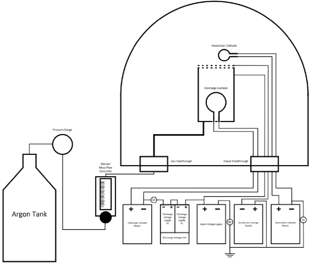
The below figure shows the full setup used:
Special thanks to MiNDS lab technician Brian Fair for supporting our use of the vacuum chamber.
2. Results
https://ieeexplore.ieee.org/document/10521066
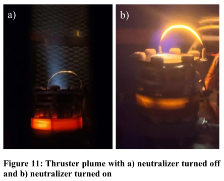

While ignition was successful, the thruster ran at an incredibly low efficiency. The following problems contributed to this low efficiency.
3. Challenges
3.1 Arcing
As seen in the results table, the accelating voltage (the voltage across the grids) was much lower than the intended 240V at around 67V. This was due to the fact that the grids were not properly cleaned or baked before testing, causing many low-resistance conduction paths to be available with the help of the plasma during operation. This triggered the power supply’s current limit, reducing the voltage that we were able to maintain across the grids.
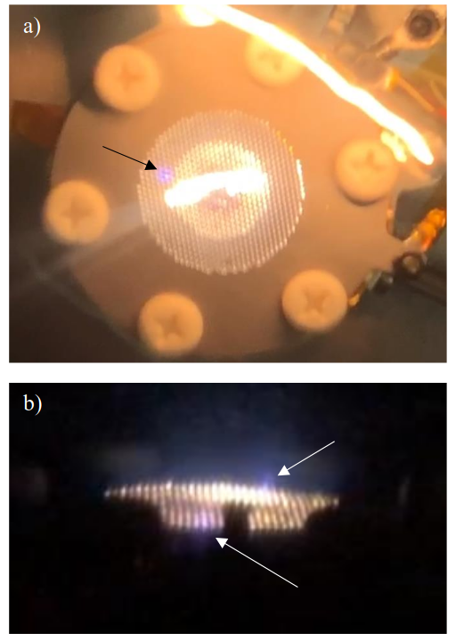
This is likely the largest contributor to the poor performance of the thruster.
3.2 Manual Flow Meter
Typical propellant flow rates for GITs are less than 1sccm. The flow rate should match the outgoing ion flow rate. Too much higher, and the high population of non-ionized gas can take heat away from ionized particles, reducing the number of ions and possibly extinguishing the plasma. Too much lower, and the plasma can get hot enough to damage the thruster by colliding with the grid or walls, also reducing ionization efficiency.
For this reason, precise flow meters are needed to run the thruster at an optimal flow rate. Unfortunately, our team was stuck with a manual flow meter with very little sensitivity below 5sccm. Therefore, we ran at a very high flow rate, decreasing the ionization efficiency.